MAX1687 datasheet pdf
| Subject | MAX1687 datasheet pdf |
| Company | MAXIM |
| Site | https://www.maximintegrated.com |
| Datetime | 09-12 |
| Download | MAX1687 |
MAX1687 Datasheet PDF Download and Image Preview.
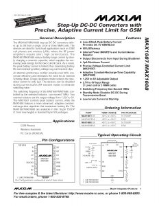
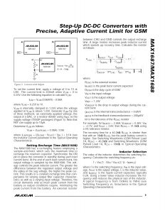
Step-Up DC-DC Converters with Precise, Adaptive Current Limit for GSM.
It provides basic pin configuration information, and includes information about internal structure block diagrams and pin descriptions.
A summary of the MAX1687 instruction set is provided. The image below is a summary. For detailed information on pinout and circuit system operation, please refer to the attached file.
Manufacturer : MAXIM
MAX1687 Features
- General Description
- Applications
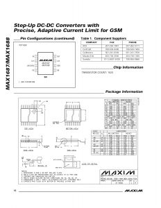
- Pin Configurations
- Ordering Information
- Typical Operating Circuit
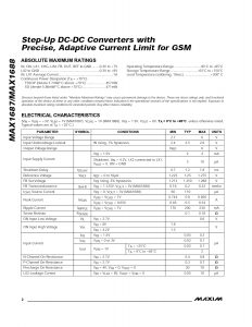
- ABSOLUTE MAXIMUM RATINGS
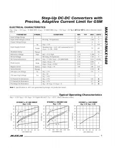
- ELECTRICAL CHARACTERISTICS
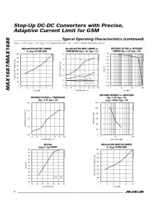
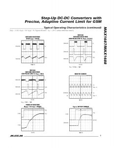
- Typical Operating Characteristics
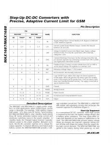
- Pin Description
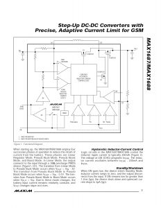
- Detailed Description
- Hysteretic Inductor-Current Control
- Standby/Shutdown
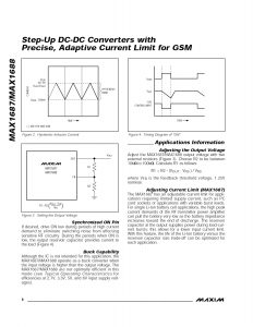
- Synchronized ON Pin
- Buck Capability
- Applications Information
- Setting Recharge Time (MAX1688)
- Inductor Selection
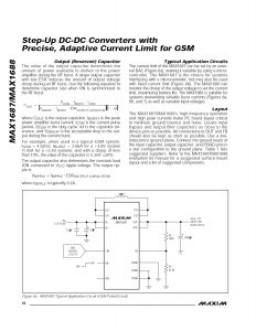
- Output (Reservoir) Capacitor
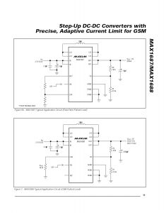
- Typical Application Circuits
- Layout
- Table 1. Component Suppliers
- Package Information
General Description
The MAX1687/MAX1688 step-up DC-DC converters deliv er up to 2W from a single Li-Ion or three NiMH cells. The devices are ideal for burst-load applications such as GSM cell phones and wireless LANs, where the RF power amplifiers require short, high current bursts.
The MAX1687/MAX1688 reduce battery surge current by slow ly charging a reservoir capacitor, which supplies the nec essary peak energy for the load current burst.
As a result, the peak battery current is limited, thus maximizing battery life and minimizing battery voltage sag and transient dips.
An internal synchronous rectifier provides over 90% con version efficiency and eliminates the need for an external
Schottky diode. A logic shutdown mode reduces the shut down current to only 3µA.
The devices can be disabled during current bursts (RF transmit mode) to eliminate switching noise.
The switching frequency of the MAX1687/MAX1688, con trolled by the selected inductor, can exceed 1MHz. Two
external resistors set the output voltage from 1.25V to 6V.
The MAX1687 controls peak battery current, while the MAX1688 features a more advanced, adaptive constant recharge-time algorithm that maximizes battery life.
The MAX1687/MAX1688 are available in thin 16-pin TSSOP (1.1mm max height) or standard 8-pin SO packages.
Leave a Reply